Given a N-Dimensional space we can think of this space as comprising a set of points (P) such that each element of this set comprises a N-tuple of (Cartesian) coordinates. This then allows us to also conceive of a corresponding negative space containing the set of points (N) each element if which comprises a N-tuple which includes at least one negative coordinate. For example if we have a 2-D space comprising 8x8 points then:
P = {<x,y>|-8<x<8 and -1<y<8}
N = {<x,y>|-8<x<8 and -8<y<8 and (x<0 or y<0)}
Thus we can define a spatial domain of discourse (U) such that:
U = P disjoint_union N
or we can define P as:
P = N\U
(The complement of the set N in the set U).
Of course the elements do not have to represent points (spatial entities that have no discernible dimension), they me represent (address) a set of uniform sub-areas into which a space in question has been divided (tesselated). This is then the fundamental idea at the heart of tesseral addressing. The distinction between Cartesian coordinates and tesseral addresses is thus that the first describe a finite point while the second describe tiles (only in the limit do they describe points).
Tesseral addressing is thus a mechanism for referencing (addressing or labelling) a N-Dimensional shape which has been sub-divided (hierarchically decomposed) into a set of isohedral (same shape) sub-spaces down to some predefined resolution. The technique was originally concerned with hierarchical clustering strategies developed in the 1960s and 1970s to improve data access times (Morton, G.M. 1996) and atomic isohedral (same shape) tiling strategies developed in the 1970s and 1980s concerned with group theory (Grunbaum and Shephard 1987). The technique was first suggested as a suitable representation for spatial applications (particularly in the domain of Geographic Information Systems - GIS) in the early 80s when ideas concerning tesseral arithmetics were first formulated (Holroyd 1983, Bell et al. 1983, Diaz and bell 1987)
With respect to N-tuple coordinate systems (such as the Cartesian coordinate system) tesseral addressing offers the following general advantages:
A N-dimensional space can be decomposed into many different forms of sub-spaces, the most common is a founded on the hyper-cube (Square in 2_D or cube in 3-D). The discussion in this document will assume this form of decomposition. We will refer to this as the quad-tesseral tessellation. Quad tesseral addressing comes in two forms: (i) hierarchical quad-tesseral addressing and (Morton) linear quad-tesseral addressing. The quad-tesseral system developed as part of the dKKBIS project is founded on the latter. We refer to this as (left-to-right) linear quad-tesseral addressing. All three approaches are described and compared below.
In general tesseral addressing systems also offer the global advantage that they can be used to model a space without reference to any specific underlying structure for data storage. Tesseral Addressing systems lend themselves to being used in many storage structures, for example B-trees (see O'Conaill 1993).
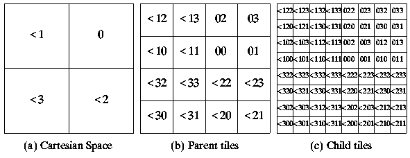
Hierarchical quad tesseral addresses (Diaz and Bell 1986, Gargantini 1983, Samet 1984) are generated in such a way as to reflect the hierarchical manner in which a subspace is decomposed (tessellated). The method of generating addresses in this manner is illustrated in Figure 1 where we consider some arbitrary 2-D positive space. We commence by assigning a tesseral address of 0 to this space. (Figure 1(a)). We then quarter this space giving each "child" quadrant a unique address to yield tiles labelled as shown in Figure 1(b). Each child address (label) is made up of a left hand symbol corresponding to its parents tesseral address and a right hand symbol corresponding to its position in relation to its siblings (i.e. 0, 1, 2 or 3). We then continue the process in a hierarchical manner by quartering these quadrants and assigning new addresses to the resulting child tiles by always appending to the right of the parent tesseral address (Figure 1(c)). We then continue in this manner (Figure 1(d)) down to some predefined resolution (depth or grain size).
Figure 1: Hierarchical quad tesseral addressing of a 2-D space
Points to note about the above tesselation:
The same process can be extended to the other quadrants of 2-D Euclidean space. However, we must identify each quadrant by associating a separate label with it. This is exactly analogous to negative coordinate addressing in the Cartesian system where the symbol "-" is used to identify such coordinates. If we label the positive quadrant with the label 0 then, so as to maintain consistency with the positioning convention used in this quadrant (Figure 1(a)), the remaining quadrants must be assigned the labels -1, -2, -3 (Figure 2(a)). We will represent these labels using a "two's complement" notation, i.e. they recur repeatedly to the left. Such digits are referred to as beaked numbers, after Diaz (1986). In this document we will represent the beaked digits, beaked 1, beaked 2 and beaked 3 using the notation "<1", "<2" and "<3". All four quadrants of Cartesian space can now be partition in the same manner as before (see Figures 2(b) and 2(c)).

Using the above form of addressing the depth of tessellation is encoded into the address length (where necessary leading zeros are included in the address so that the appropriate length is maintained). Consequently addresses must be stored as strings of characters of variable length. th is maintained). Alternatively, we can use some sort of bit pattern which comprises a set of bits to store an address and a further set of bits in which to store the depth (see Gahegan 1989).
The advantages of hierarchical quad-tesseral addressing compared with other tesseral systems (see below) is that large uniform spaces can be referenced by a single address while detailed spaces can be decomposed into sub-addresses and so on (see Figure 3). This then has implication with respect to data storage efficiency. The disadvantages of then system (again compared with other tesseral systems) are that translation and rotation are both complex and expensive (when implement using standard processors).
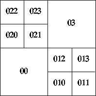
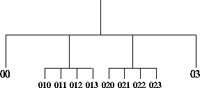
Given a quad tree of the form given in Figure 4 then clearly such a tree can be linearised in that it can be traversed from left to right to produce a linearisation. This is an important feature of tesseral addressing which has implications for both storage, and comparison and translation of groups of addresses.
With respect to data storage linearisation allow sequences of addresses to be stored simply in terms of the start and end address of the sequence. This is usually referred to as run-line encoding. Given such a sequence it is a trivial matter to establish whether a certain address is contained within it or not. Similarly, a sequence of addresses can be translated simply by adding/subtracting to/from the start and end addresses.
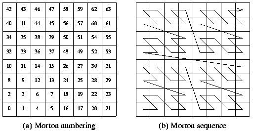
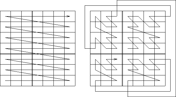
Linear quad tesseral addressing is similar to the hierarchical form described above except that that the decomposition is carried out uniformly so that all sub-spaces are decomposed down to the same level of resolution. The principal advantage of this is that the space is linearised in a uniform manner and that the superimposed arithmetic is more tractable. Such a linearisation is present in the hierarchical form however its nature is often confused (Figure 3). If we consider the space given in Figure 1(d) and assume that the addresses given represent integers to the base four it is possible to convert these numbers into decimal numbers as shown in Figure 5(a). Such numbers are referred to as Morton numbers after Morton (1966). The significance of these numbers is that they clearly indicate the linearisation (Figure 5(b)) often referred to as the Morton Linearisation.
The hierarchical quad-tesseral addressing system cannot be linearised so obviously. However, if we consider the quadtree representation associated with this addressing system presented in Figure 4 then clearly such a tree can be linearised in that it can be traversed from left to right to produce a linearisation.
Tesseral arithmetic is essentially translation, the translation distance being the number added/subtracted. Thus addition of 1 to any tile is to move a distance equivalent to the distance (and direction) that the tile 1 is from 0. For example addition of 1 to 1 moves from tile 1 to tile 10 (see Figure 1(c)). By extension tesseral subtraction is merely translation in an opposite direction. Thus we move a distance equivalent to the distance the tile is from 0 but in the direction not from zero to the tile, but the opposite direction.
The following description is based on Bell and Mason (1990); readers requiring further information are thus referred to this paper. We will first consider linear tesseral addition and then go on to consider subtraction.
To add two tesseral addresses we must make use of an addition table which produces a result for the addition of any two of the symbols used ({0 .. 3}). Such a table is given in Table 1. The construction of this table is well understood and is described in Bell et al. (1983).
| 0 | 1 | 2 | 3 | |
|---|---|---|---|---|
| 0 | 0 | 1 | 2 | 3 |
| 1 | 1 | 10 | 3 | 12 |
| 2 | 2 | 3 | 20 | 21 |
| 3 | 3 | 12 | 21 | 30 |
Physically, the addition of 1 corresponds to a movement from tile 0 to tile 1, i.e. a horizontal translation of 1 tile at the relevant depth. Similarly, the addition of 2 corresponds to a vertical translation of 1 tile and the addition of 3 represents a diagonal translation. These physical interpretations must be made at a consistent depth. For example, the addition:
3 + 1 = 12
corresponds to the translations 03 + 01 -> 12 and 003 + 001 -> 012, i.e. a horizontal movement of tile 03 at the resolution of Figure 1(b) or of tile 003 at the resolution of Figure 1(d).
Multi-digit addition is performed by using a carry in a fashion exactly analogous to ordinary arithmetic with numbers expressed to the base ten. Examples:
Operands       221       113       021       013       201       210
Operations     011 +     020 +     303 +     213 +     102 +     023 +
               ---       ---       ---       ---       ---       ---
Answers        320       133       332       330       303       233
               ===       ===       ===       ===       ===       ===
Carries        11                   1        33
The above operations can be checked with reference to Figure 1(d). Note also that using this arithmetic we can generate addresses outside our entity space. However, for the tesseral spatial reasoning system described here, such addresses are considered to be invalid.
If desired we can produce a similar table to include the addition of beaked numbers.
Subtraction is provided by an extension of the methods used for p-Adic fields (Koblitz 1977) to a given base. This is well described in Bell et al. (1986) where it is presented as follows. Given two tesseral addresses A and B, if we subtract A from B we will produce a third tesseral address X:
B - A = X
or
A + X = B
We find the digits for X from right to left starting with the least significant digit of X. Thus if A is equivalent to the tesseral address 021 and B is equivalent to the tesseral address 302 then the last digit of A will be 1, the last digit of B will be 2, and thus the last digit of X will be such that when we add it to 1 we get 2. From Table 1, given these figures, we can see that the last digit for X must then be 3:
1 + 3 = 1,2
Thus X = --3. Removing the last digits from A, B and X and applying the carry 1 to A (with its last digit removed) we get:
A + 1 + X = B
Where A, X and B represent the numbers A, B and X with their right most digits removed. Thus:
02 + 1 + X = 30
03 + X = 30
The last digit of X will now be such that when we add it to 3 we get 0. From Table 1 we can see that the last digit of X must be 3:
3 + 3 = 3,0
Thus X = -33. By removing the last digits from A, B and X to get ( A", B" and X") and by applying the carry 2 to A" we now get:
A" + 3 + X" = B"
0 + 3 + X" = 3
3 + X" = 3
The last digit of X" will now be such that when we add it to 3 we get 3. Reference to Table 1 now demonstrates that this must be 0. Thus 302 - 021 = 033. We can test this by adding 033 to 021.
Should the result of a tesseral subtraction give a tesseral address located in one of the remaining three tiles of Cartesian space which are outside our entity space the final digit of X will repeat indefinitely. This is referred to as a beaked digit after Diaz (1986). However, given that we are only interested in the positive tile of Cartesian space in this paper we will not consider this eventuality in any further detail here.
To automate the above process we can make use of a subtraction table as shown in Table 2. This Table can then be used to "lookup" the required "X" digit and the associated carry to be added to the remaining digits of "A". The table is entered with the appropriate "B" digit along the X-axis and the associated "A" digit along the Y-axis. For each entry the carry is given first and then the "X" digit second separated by a comma.
| B | ||||
|---|---|---|---|---|
| A | 0 | 1 | 2 | 3 |
| 0 | 0,0 | 0,1 | 0,2 | 0,3 |
| 1 | 1,1 | 0,0 | 1,3 | 0,2 |
| 2 | 2,2 | 2,3 | 0,0 | 0,1 |
| 3 | 3,3 | 2,2 | 1,1 | 0,0 |
Examples:
"B"       120        300        310        311        321        331
"A"         1 -        2 -        3 -      013 -      120 -      132 -
          ---        ---        ---        ---        ---        ---
"X"       031        122        123        122        201        023
          ===        ===        ===        ===        ===        ===
Carries   11         22         23         22                    22
Again we can check these results with reference to Figure 1(d).
From the above it can be seen that tesseral addressing does not readily support simple human interpretation. It is therefore essential that any tesseral technique also readily provides for translation to and from a more intelligible (Cartesian) coordinate system. With respect to the linear quad tesseral representation this is best achieved through a process known as bit interleaving.
We refer to the above system as Morton linear quad tesseral addressing because of the Morton linearisation that results. An essential feature if the system is that the addressing system is still founded on ideas concerning the decomposition of space into isomorphic (same shape) sub-spaces. We can dispense with this hierarchical decomposition and simply consider the addressing of some space at a particular resolution. Let us consider a 4-D space cast into a set of isohedral sub-spaces at some predetermined resolution such that each sub-space is reference by a 4-tuple of (Cartesian) coordinates and lets call these coordinates x, y z and t (time?). Let us also assume that the address is to be represented using a 32 bit signed integer. We can now assign groupings of bits within this integer as follows:
S 4444444 33333333 22222222 11111111
where S is the sign bit, and the integers 1, 2, 3 and ^ 4 represent the bits to be associated with particular coordinates used to reference 4-D space. Note that:
In order to identify the coordinate groupings a base must be allocated to each group. In the above case the following are appropriate:
BASE1 = 1
BASE2 = 256
BASE3 = 65536
BASE4 = 16777216
Each base represents the integer that must be applied to a particular coordinate so that it is encoded using the appropriate grouping of bits. With respect to this document the dimensions to be associated with the BASE1, BASE2, BASE3, BASE4 groupings are labelled as X, Y, Z and T, although any other labelling could equally well have been used.
Given the above we can define a function Fcartesian2tesseral that converts its argument (a 4-tuple in this case) to a tesseral address:
Dom(Fcartesian2tesseral) = { | The set of all  tuples}
Cod(Fcartesian2tesseral) = {a | The set of all tesseral addresses}
Gr(Fcartesian2tesseral)  = { | a = x + BASE2(y) + BASE3(z) + BASE4(t)}
We can define a similar function, Faddress2cartesian, to perform the reverse conversion.
The advantages offered by this approach (over other forms of tesseral addressing) are:
Created and maintained by Frans Coenen. Last updated 07 January 2008